Get started with Arduino
Connect boards such as ESP8266 and ESP32 to an IOSignal server and exchange signals with web apps, other boards and Node.js. If you are new, read core concepts in five minutes first; tags, delivery types and the home channel are the same in every environment.
| Use | What it does | Where to start |
|---|---|---|
| Messaging | Channel and CID messaging, authentication and encryption | IOSignal for Arduino, D1 mini and ESP32-C3 channel messaging, arduino.iosignal.net |
| Devices | Devices the remocon.kr web app finds and controls (name, buttons, state) | The examples below, Build a device (app.iosignal.net compatible), arduino.iosignal.net |
Both are in one library, IOSignal. Since 9.23.0 the device examples and the device helper headers (IOSignalUi.h and others) are in IOSignal too; before that they were in the Remocon library.
1. Install
Install IOSignal (9.23.0 or later) from the Arduino IDE Library Manager. The steps are in library installation. To see something working before touching code, flash firmware with install from the browser below.
2. First connection
Upload D1 mini and ESP32-C3 channel messaging. Pressing the button sends a signal on the #homeButton channel, and receiving one toggles the LED. Enter Wi-Fi on the board settings page with the board on USB.
3. What differs on Arduino
- One receive callback: every signal arrives in
onMessage(tag, type, payload, size); comparetagto tell them apart. There is no JS-styleon()orlisten(). - Subscribe in
onReady:onReadyruns on every connection, reconnections included. Put subscriptions and the first announcements there. - TCP: boards connect to the server's TCP port (
io.iosignal.net:55488on the public server), not to WebSocket. Do not putws://in the host. Connections - Receive buffer: 80 bytes by default. The server does not send larger messages to the board. To receive long messages such as other devices' names and state, enlarge it with
setRxBuffer()beforebegin(). - Board settings: ESP examples take Wi-Fi, server and device key from a browser over USB, and the board stores them. Board settings
- Authentication: logging in with a device key gives a fixed CID. When the same key logs in elsewhere and replaces this board, the library stops. Authentication clear and logs
4. Build guides
| What you want to build | Pages |
|---|---|
| Boards and the web exchanging channel signals | D1 mini and ESP32-C3 channel messaging, tags and delivery types |
| A device the remocon.kr app finds and controls | Build a device (app.iosignal.net compatible) |
| Relays controlled by buttons on other boards | Device setup example: relays and button controllers |
| Binary data and numbers with JS | Payload formats and JS–Arduino compatibility |
| Logging in with a device key | IOSignal for Arduino, server authentication |
| Looking up methods, callbacks and constants | Arduino API |
5. Examples: install from the browser
ESP example pages on arduino.iosignal.net carry prebuilt firmware. You need only a USB cable and a browser, no Arduino IDE. The site is in Korean.
- Open the example page in desktop Chrome or Edge (Web Serial is required; iOS is not supported).
- Connect the board over USB, press the install button in the firmware section and choose the port.
- When the install finishes, enter the 2.4 GHz Wi-Fi name and password in the window that follows. To change them later, use the board settings page.
- Open remocon.kr on a phone or PC on the same router, and the device card appears.
- The firmware holds no Wi-Fi password or device key and connects with an anonymous CID. A device key and server can be set in the board settings (board settings).
- If the board already runs firmware with IOSignal board settings, the install is an update and the stored Wi-Fi stays.
- Close the serial monitor first if it holds the port.
- The same sketches are in the Arduino IDE under File → Examples → IOSignal.
Each card opens the example page on arduino.iosignal.net (wiring, signal flow, firmware install, web control screen). "Not tested on hardware" marks an example whose description was written from the code and not yet checked on a real board.
One board, one card
One board becomes one device card in the app. Start here to see how discovery, commands and state flow.
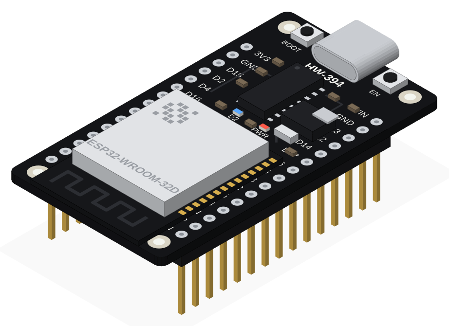 ESP32 CID LEDESP32 dev boardTurns one LED on and off with CID commands. The shortest example of discovery, commands and state.
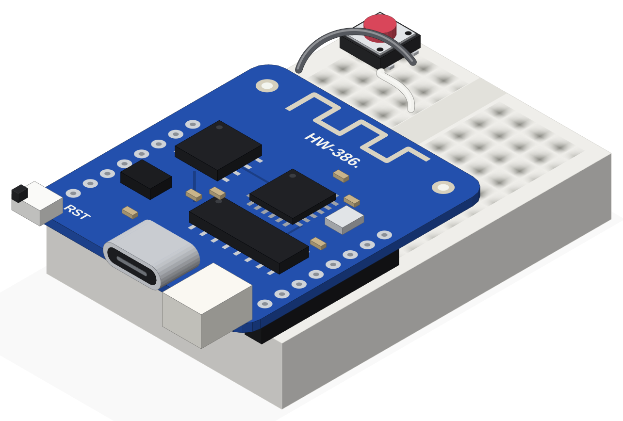 D1 mini LED and buttonESP8266 D1 miniTurns the built-in LED on and off from the web app and a button.
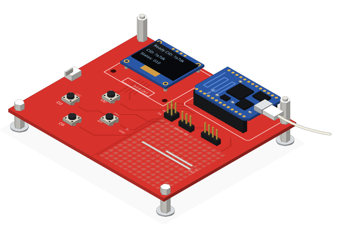 Remocon8266 basicRemocon8266 board (D1 mini based)Controls three outputs as a 3-gang switch and shows the state and who changed it on the OLED.
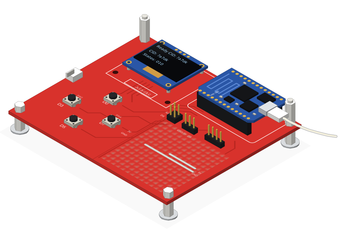 Remocon8266 tvRemocon8266 board (D1 mini based)Controls a bayo.tv screen with four buttons and shows playback, volume and title on the OLED.
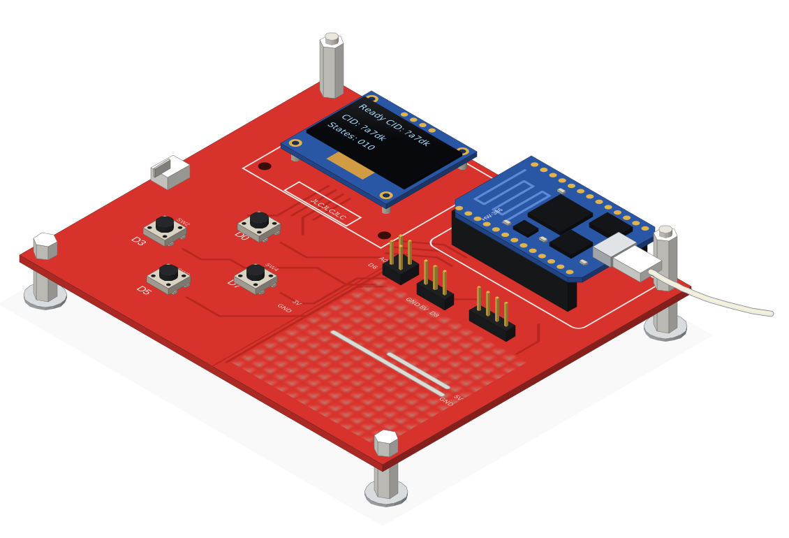 Remocon8266 scannerRemocon8266 board (D1 mini based)Sends #search like the app and lists the devices on the same router, with their state, on the OLED.
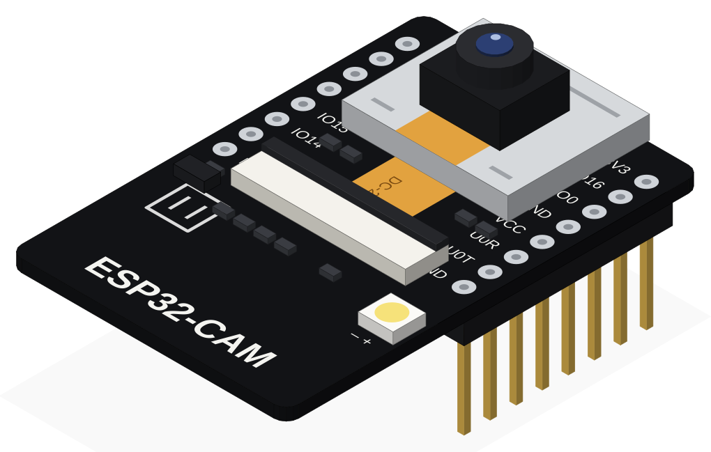 ESP32-CAM cameraESP32-CAM (AI Thinker)Shows its photos on the remocon.kr device card. An E2E key can encrypt the photos.
Groups
Several boards share one state. The app shows one group card however many boards there are.
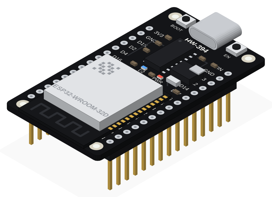 ESP32 group LEDTwo ESP32 dev boardsTwo boards share the #lab group; one 2-gang switch in the app controls each board's LED.
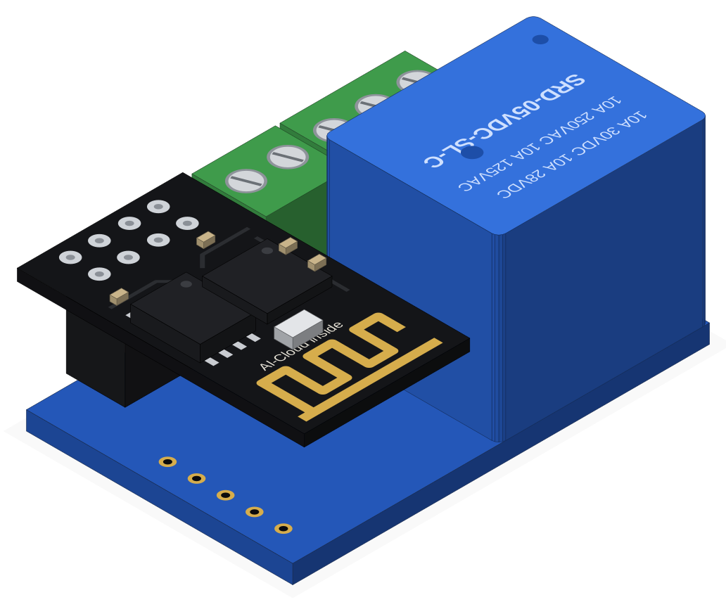 Wi-Fi shared switchESP-01, D1 mini, ESP32, ESP32-C3The simplest example: prints the #switch group state to serial. Board settings turn it into a relay or button board.
Relays and button controllers
Switch a relay board from the app, or control it from another board with buttons. A controller's target CID and what each button does are board settings, so they change without new firmware.
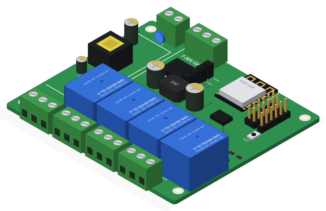 ESP8266 4-channel relayESP-12F 4-channel relay boardControls four relays with the relay4 type screen.
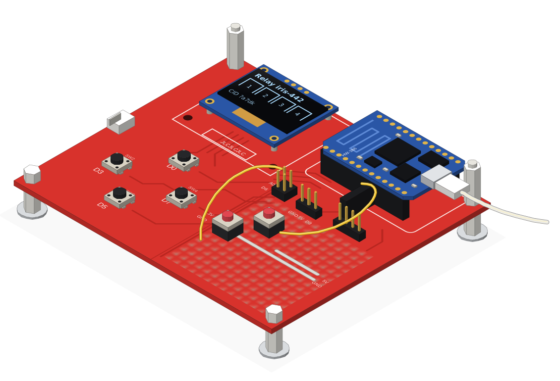 Remocon8266 button controllerRemocon8266 board (D1 mini based)Five buttons control another device by CID (default: the 4-channel relay) and the OLED shows its state.
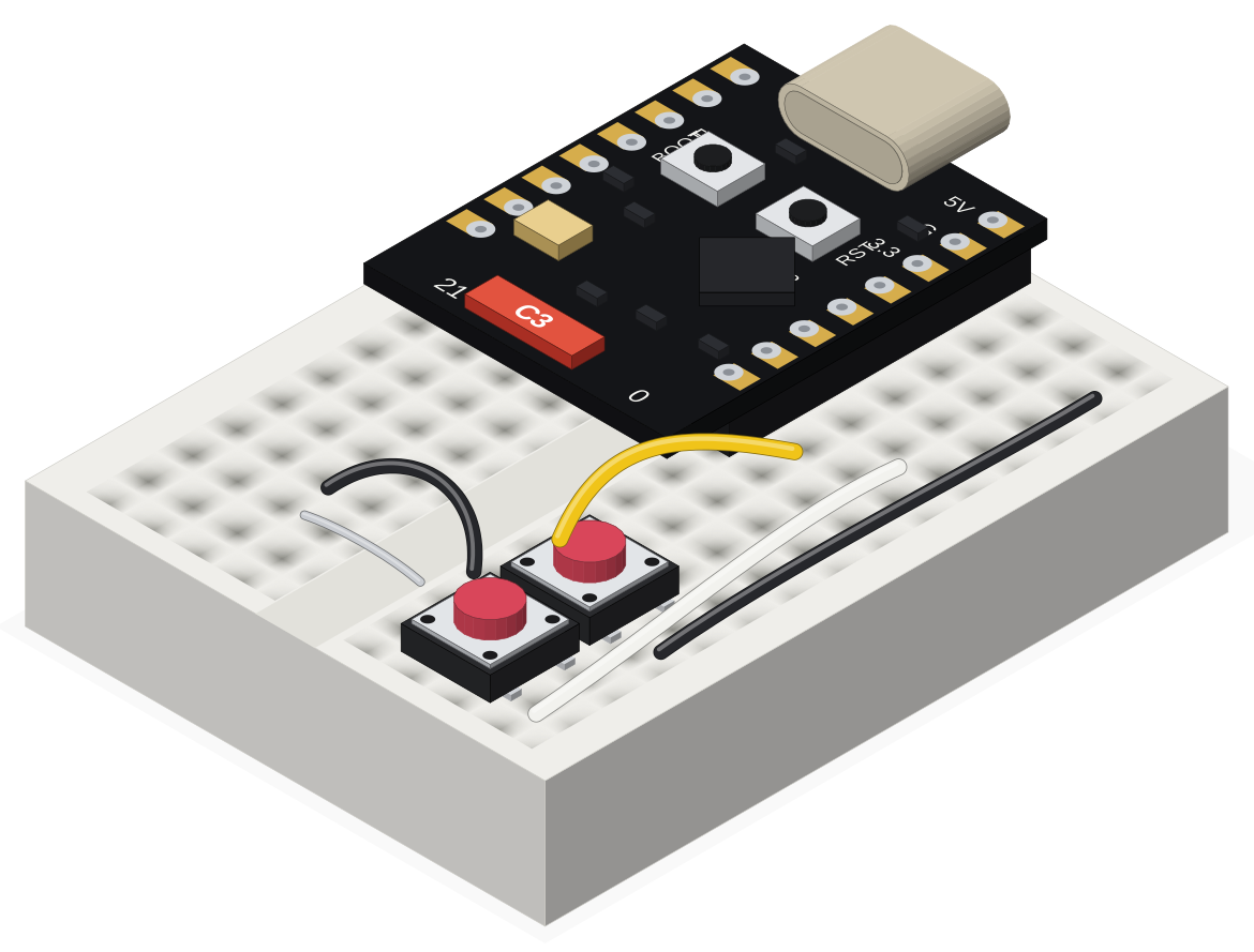 Two-button controllerD1 mini, ESP32, ESP32-C3, ESP32-S3Two buttons on any ESP board control relays, lights or groups.
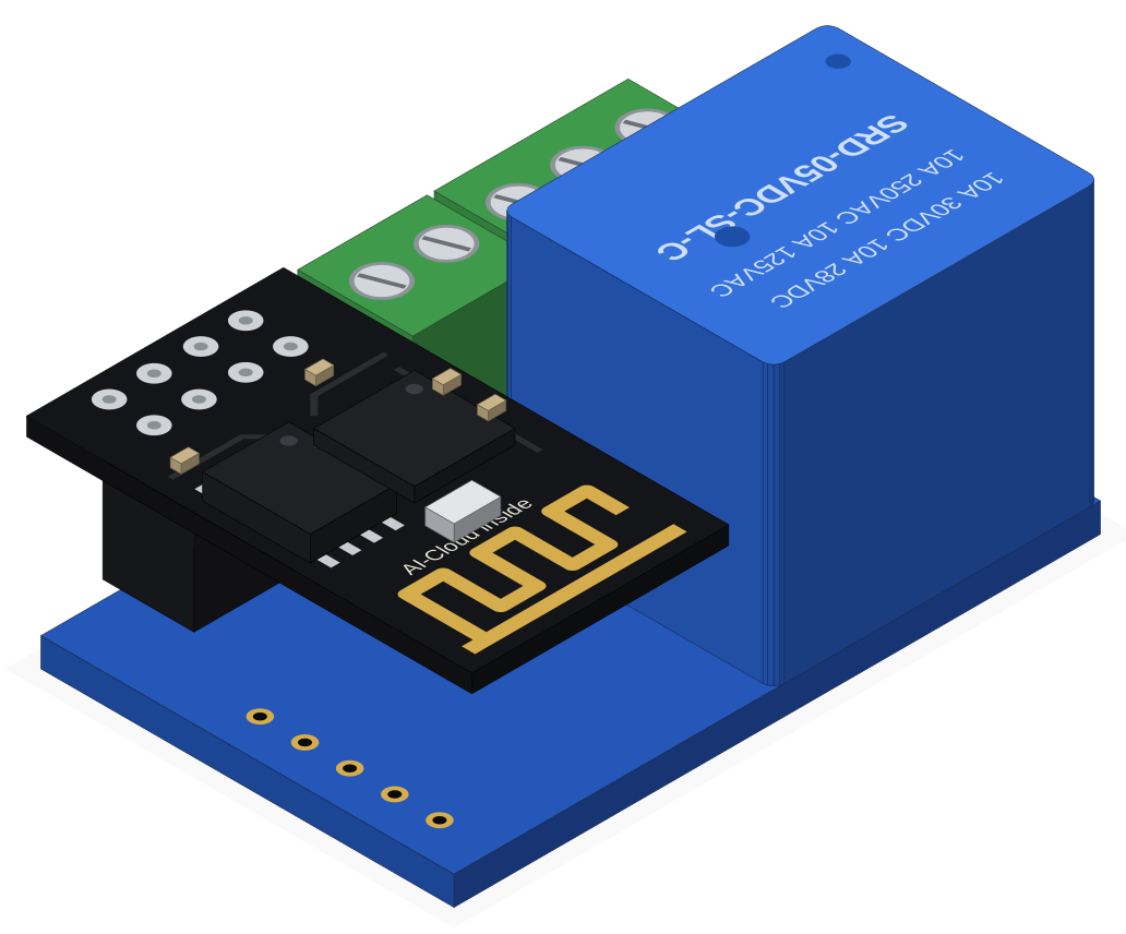 ESP-01 relay and buttonESP-01 (ESP8266)Controls a relay and an LED as a 2-gang switch; a button also switches the relay.
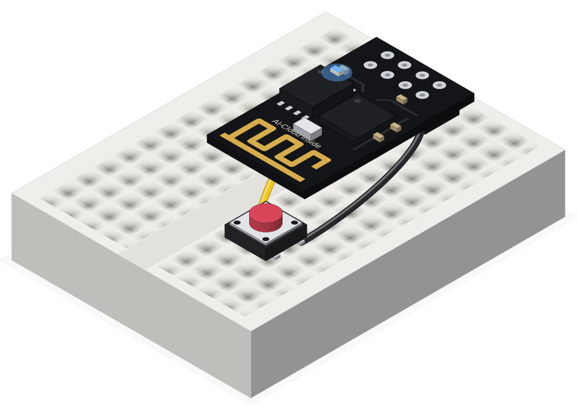 ESP-01 button controllerESP-01 (ESP8266)One button controls another device and the built-in LED shows the target's state.
iris board
Five ways to use the same iris board (ESP32-C3, four built-in RGB LEDs, two buttons, DIP switches). Start with iris basic; with two boards, pair it with the iris-basic controller.
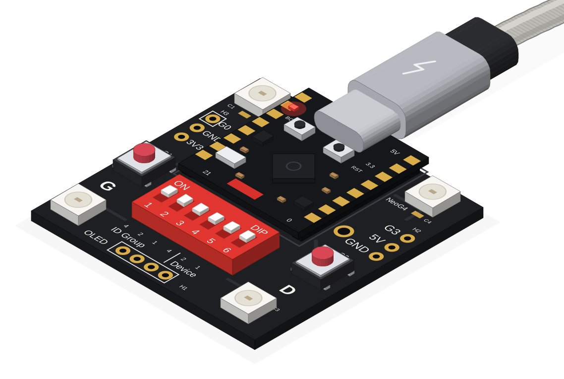 iris basiciris board (ESP32-C3)Turns the four built-in RGB LEDs on and off as a 4-gang switch.
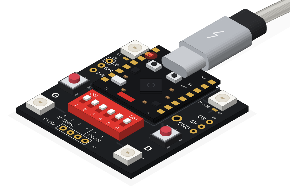 iris-basic controlleriris board (ESP32-C3)Finds and controls an iris-basic board like the web app does, and mirrors its state on its own LEDs.
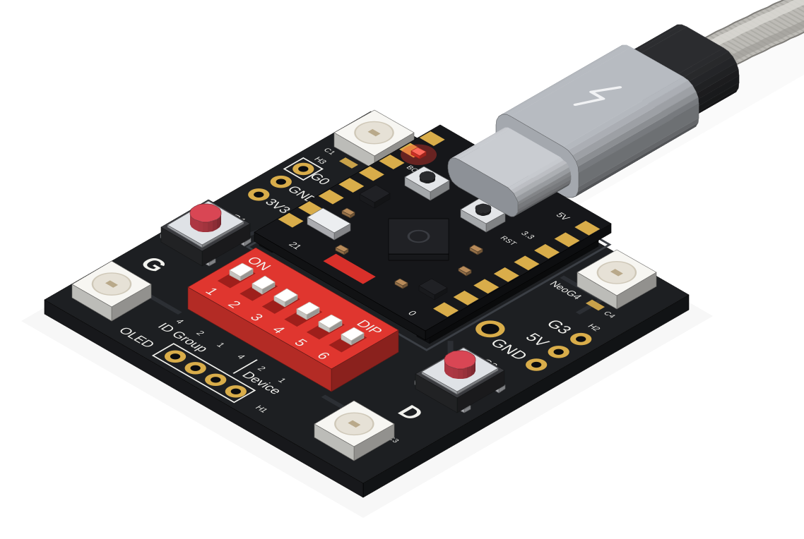 iris button controlleriris board (ESP32-C3)Two buttons control another device; four LEDs show the target's channel state.
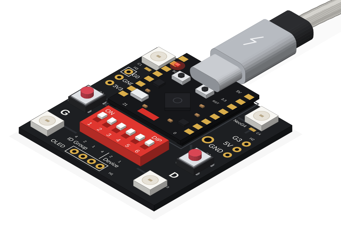 iris RGB lightiris board (ESP32-C3)Sets hue and brightness of each of the four LEDs, with the iris screen (iris.2).
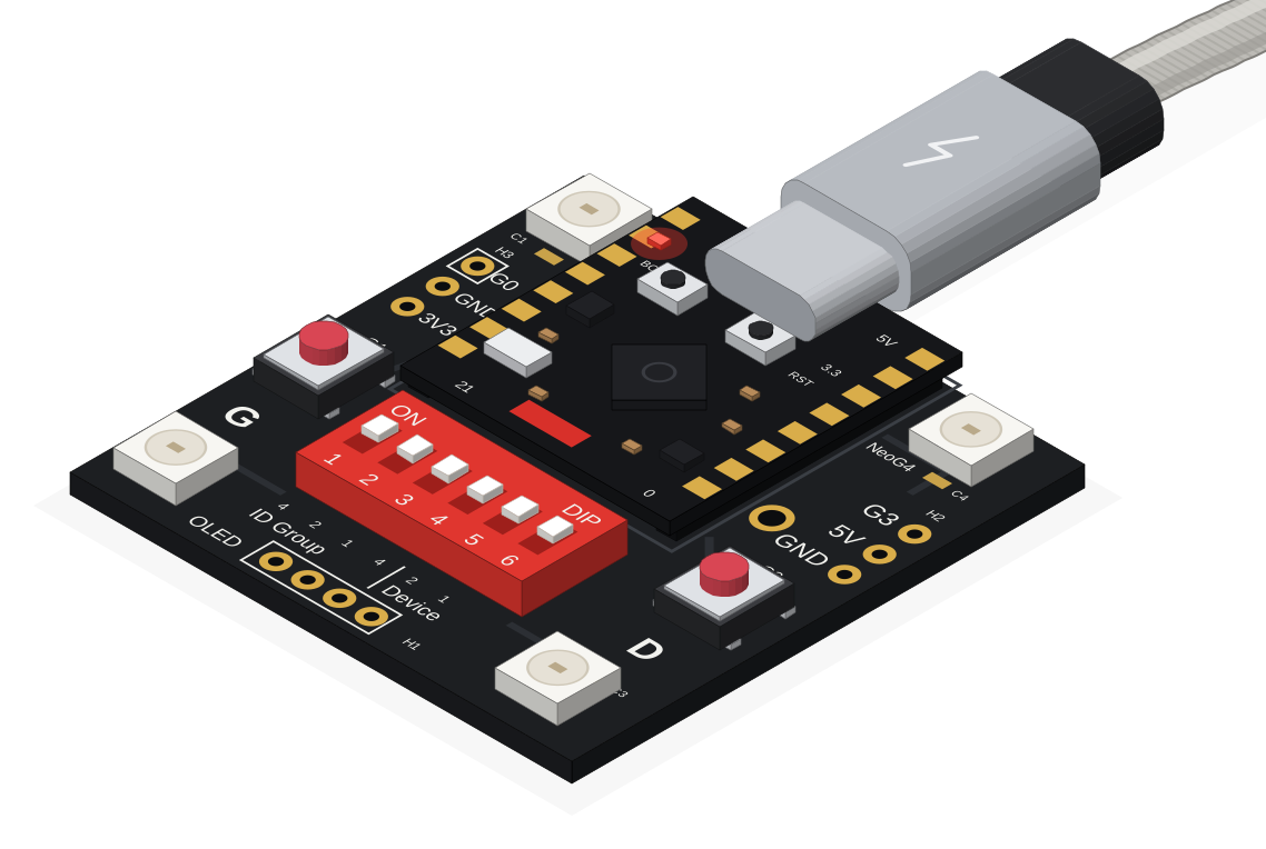 iris group lightSeveral iris boards (ESP32-C3)Boards share an 8-gang switch state; DIP switches set the group and device number.
Examples without browser install
- The Arduino UNO R4 WiFi example (
uno-r4-wifi-heart) is uploaded with the Arduino IDE. It is described on arduino.iosignal.net. - Messaging examples that are not devices (channel messaging, duplicate login) are on arduino.iosignal.net. The first tutorial is D1 mini and ESP32-C3 channel messaging.
6. When you are stuck
- If the board does not reach the server, go through connection diagnosis.
- If a device does not appear in the app or its output does not change, see device troubleshooting.
- Common mistakes are collected in the FAQ.